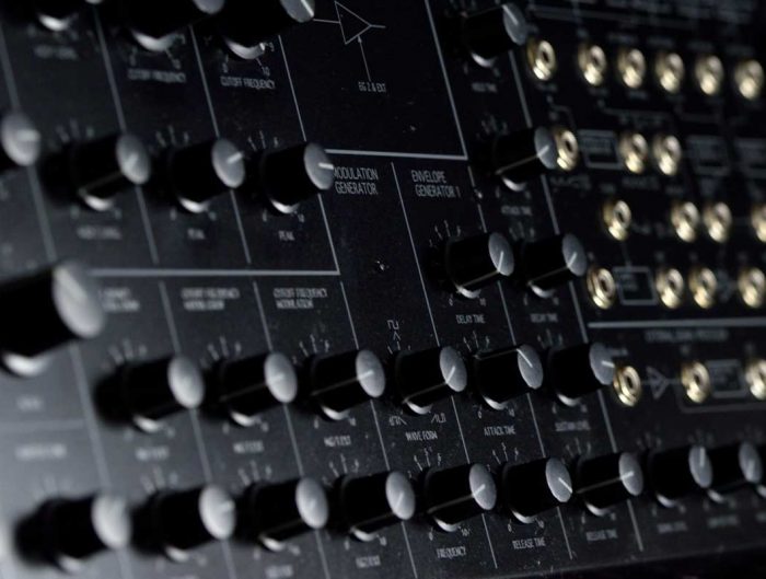
As part of my custom modular synth build, I selected the Neutron Sound Orgone Accumulator as one of the oscillator modules alongside an the analogue Haible Living VCOs by Random Source. You can read about the selection process here. I’ll be blogging about my experience building some of the key modules for this project.
The Accumulator is a digital oscillator built on the Teensy ARM micro-processor. What’s great about digital is the flexibility to be re-programmed, and all the code is available on GitHub. In order to get started I’ll need to get all the parts!
Ordering the parts
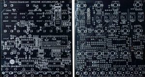
First I ordered the PCB, or printed circuit board. This will house the microprocessor, potentiometers / controls, inputs and outputs, and all the electronics and power to integrate these together. In the case of the Accumulator it’s a single PCB suitable for Eurorack, available with or without a front panel. For my project I will build a single front panel for all modules, so this wasn’t required.
The PCB was US$38 or AU$52.47 including shipping to Australia.
Regarding the BoM or Bill or Materials, Neutron Sound provide one on their website. I copied it all into a Google Doc, then marked off each item as I ordered it. I ended up getting all the electronic components from Mouser, which cost AU$99.59. All the Mouser codes are provided on the BoM which is great. I already had the Thonikonn 3.5mm jacks for audio and control voltage connections from a 50 pack I’d previously bought, and the jacks for the Accumulator came to AU$5.50.
I sourced the Teensy processor locally from Little Bird Electronics including a USB cable for AU$50.63.
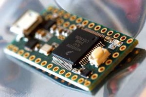
The Teensy processor
The potentiometers I order from Small Bear along with the units for my Living VCOs. It was quite a quick delivery similar to Mouser, and the packing was more sensible. These were the last items I ordered.
Building the digital oscillator
Once all the parts came in I was ready to build! Neutron Sound provide a build manual so to that first! Initially it says to program up the Teensy, but I decided to skip that and get to assembly as I felt in the mood for some soldering.
I decided to sort through some of the Mouser bags initially to speed things up later, so I separated all the component types between, resistors, capacitors, diodes, hardware such as sockets, op amps, regulators etc.
You can see from the photo there’s a lot of plastic bags from Mouser. The labels make it easy to sort, but from an environmental perspective one bag for a resistor is ridiculous. This is something I’ll consider in the future when I order parts.
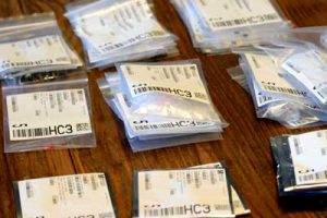
Sorting the many component bags from Mouser
I began by following the manual.
Solder in the four IC sockets
This was a straight forward process and only required some minor touch ups along the way. I used masking tape to hold the sockets in place when I flipped over the PCB to solder.
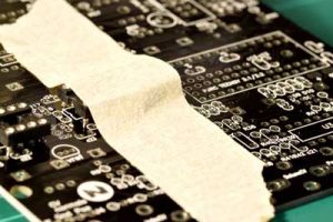
Holding the IC sockets with masking tape
Solder in the 12 Diodes
The diodes were slightly trickier as they only go in one way, as guided by the PCB markings. They are also mounted vertically which saves space and isn’t much harder to work with. I carefully installed them one by one.
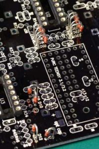
Installing the diodes
Solder in the 54 Resistors
Resistors are simple as they aren’t polarised, and can be installed either way. Like the diodes they are vertically mounted. I decided to solder in each value of resistor as I opened that packet, placing them all in the PCB prior to soldering to save time. I double checked all the the PCB markings and build guide as I went along, as errors cost time.
Sometimes it took a while to find a resistors place, as the numbers jump around a bit. Also, some of the spacing was very tight, e.g. between the resistors and the diodes, but they stay sufficiently separated and I can understand that fitting everything on a single Eurorack PCB is a challenged! I visually inspected each soldering point just before cutting the legs.
I found one discrepancy on the parts list, which stated 1 watt for the 10 ohm resistors, however the part number is actually for a 1/2 watt, although to real problem here.
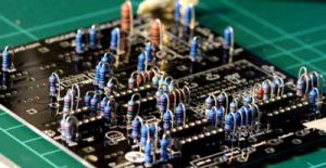
Installing the resistors
Solder in the Power Header
This one was nice and easy; just ensure it goes in the right way round! I taped it to keep it in place. The Mouser part number I received was different to the BoM, but it was a standard power header so I soldiered on.
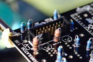
Installing the IC sockets
Solder in Button 8
This needs to be done before the rest of the headers. The main recommendation is to ensure it’s flat so it lines up with the panel at the end. Regarding orientation there’s a hole on the PCB which lines up with a notch on the bottom of the switch. This saves you from getting in the wrong way around, in which case the state of the switch would be swapped.
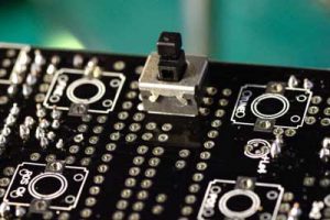
Installing button 8
The Teensy
The next steps involved the Teensy processor. Given I skipped the programming steps to get into the building, it was time to do this.
The first step was to install the Arduino 1.0.6 IDE and the Teensyduino software from the link provided. I downloaded and installed Arduino first, then the Teensy. For Teensy you have to specific the location of the Arduino app; that’s as complicated as it got.
Next was connecting the Teensy via USB. Blinking light… good! Open Arduino, set to Teensy, run the sample program and change a setting to get LED to blink. Well that’s the instruction. It seems my Teensy was already programmed to blink, and even the LED pin was already set to 13.
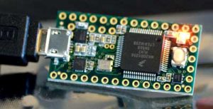
Programming the Teensy
Next was downloading the firmware code from Github and loading it into the Arduino. I’ve noticed there’s also the overclocked version for higher resolution, but I decided I’d come back to that once everything was working normally. So I went with the Orgone Accumulator 2.0 official file. At this stage all the tabs open up and you can see all the different parts of the code which make the oscillator work, including all the wave tables. You can definitely appreciated the effort required to get this done! Verifying / compiling and uploading the code takes only a matter of seconds. Firmware installed!
The next steps involved getting the Teensy dirty! Part one is separating the USB and 5V power but cutting a pad. However I flipped my Teensy over on my clamp and saw that this was already cut! I’d later find out that it looked cut, but it wasn’t. Back to this later.
Next were the pins, which definitely needed some work! You need to solder on three sets of pins, including one SMD one which I hadn’t done before, then mount another row of pins. The instructions were nice and clear about how to do this. I opened all the header bags to ensure I had the correct ones. Again, some of the Mouser packaging here is ridiculous (a bag within a bag, bubble wrap and foam etc). The rows of pins could easily be broken off by hand (for 7 pins, less required a cutter), and I soldered these first by sitting the first one down on a right angle. On visual inspection they didn’t come out perfect 90 degrees, but this didn’t prove to be an issues once the headers were put on.
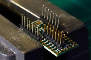
Installing the pins
I found that I had to use my vice to solder in the SMD pins, otherwise it wouldn’t stay still. I realised after that I didn’t use the fourth pins to align the SMD header properly as per the instructions; it pays to read a page ahead! Despite this my alignment was fine, and after that I aligned the last pins properly as per the instructions. My first experience with surface mount was good, and it was no more difficult than through hole, although I’d imagine it’s trickier with components and anything less spacious like an IC.
I wired in the pins although became concerned with a tiny bit of solder or flux that seemed to fly off between two pins of the processor. I took this photo to see what was happening. Disaster! I though first I’d try a push it off with a pointy nose. This seemed to work and I managed to scrape off the residue, feeling lucky at this point.
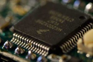
Solder blob on the Teensy processor
I then put on all the headers over the pins, and it was time to align to the main PCB. I found this was possible after a few attempts and some jiggling around. Then I soldered it all in place.
The Regulator
There’s two options to power the board; via a 5 volt source, or a 12 volt source with a 5 volt regulator. As I haven’t selected power distribution, already had the voltage regulator, and most of the other modules will run on 12V, and I decided to use it. It only requires to be soldered as per the markings, and a jumper to be soldered across.
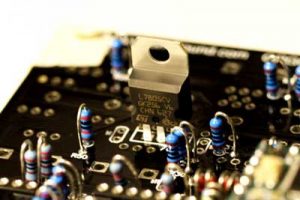
Installing the regulator
Trimmers
There’s two trimmers required for tuning and 1v/Oct control voltage adjustments. These can be mounted on either side, however I mounted them in the standard way where they can be adjusted without opening the synth up. I soldered one leg first, then heated it and pushed it in by hand to get it flush against the PCB.
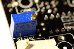
Installing the trimmers
Voltage Reference
The single voltage reference was then put in as per the markings. For mine the legs didn’t require any bending. This was the trickiest component to solder so far. The legs are very close together, and the solder pads are quite small.
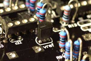
Installing the voltage reference
Ceramic and Film Capacitors
Wait a minute, shouldn’t these already be done? On most builds you do them right after the resistors. As it turns out, I skipped the page and seeing the electrolytics in the manual later I thought nothing of it. Silly mistake; probably due to the fact I’ve been completing parts of the installation whenever I’ve had spare time, so concentration hasn’t been as focused. A good lesson nonetheless.
There was a second concern also. The build guide is saying 20 x 1000pf capacitors, but I only ordered 18. The BoM also says 18. Counting the capacitor numbers on the build guide, C3-17, C19, C21, C22, that’s 18. So the build guide is incorrect, relief on my part! At this state I decided to take out the Teensy in order to avoid any issues, and was able to slowly pry it out.
The bypass capacitors were a little tricky as some the markings are illegible. I used the images throughout the build guide to provide some confidence regarding the correct positions.
In the end, despite completing them in the wrong order, it was relatively simple to retrofit these capacitors. I only had to work around the headers a little.
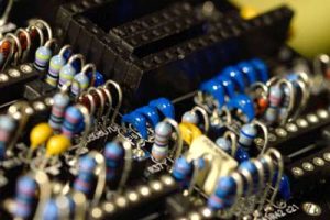
Installing the ceramic and film capacitors
Electrolytic Capacitors
Only the two of this bad boy. They are polarised so you must put them in the correct way around. This was straight forward, although the solder preferred sticking to the legs rather than the solder pads.
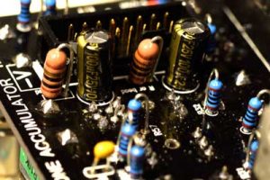
Installing the electrolytic capacitors
So that’s the capacitors… but I have one more electrolytic! After checking it’s value of 10uf in the BoM, I realised this isn’t in the main part of the build guide. The note in the appendix is “replace the b9 bypass with this, positive terminal facing the bottom of the board (where the jacks over”, and I added a note in my ordering document. But I’d already installed b9, so it was time to remove it.
b9 is one of the capacitors with poor markings on the PCB, and easily confused with b8, so I used another diagram in the build guide to determine which one it was. I used my solder sucker to suck as much solder as I could, then used tweezers to grab the capacitor and try and pull out each leg while hot. It wasn’t easy but eventually I got it out, and luckily the holes were still present, or so I thought. To fix a hole I had to put some solder in and suck it all out again. The second one wouldn’t clear though, so I put a blob of solder, heated it up while pushing the capacitor through, and after many attempts, during which I realised it was difficult to heat both sides of the PCB and I needed a little more temperature, it was finally in.
The rest of the switches
These were a straight forward affair. To get them flush I followed the advice by soldering a single pin first, then checking the alignment.
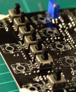
Installing the buttons
Potentiometers
Herein lies one of the issues with my project. As I am building a custom front panel, I have nothing to align the potentiometers and LEDs to. So what to do… I could build a set of dummy panels, or put a slight tolerance in my holes, at the risk of them being seen. But what’s to say the LEDs are at the right extrusion length?
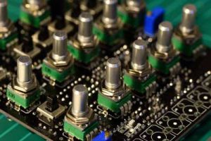
As the potentiometers have an natural “seated” position, I decided I’d solder them in that position, then add at least 1mm to the hole sizes in the panel. I could also measure the exact final distance between components before committing to the spacing in the panel. I also took the recommendation and increased the soldering temp a bit for this.
The trickiest thing about the soldering here was working around all the other components, but it wasn’t too bad, it just required more care. At this stage it was starting to look like a real module!
LEDs (light emitting diodes)
There’s only four of these, but how much to protrude them is an issue when there’s no front panel yet. Taking a look at some of my gear, some have them sticking out a little, however the Doepfer Dark Energy has them sitting just behind the panel. I figured it would be easiest to have them aligned with the top of the potentiometer nuts, roughly where the panel would finish so they’d finish similar to the Dark Energy, if not slightly more protruded.
So, quick reminder that long leg is positive and time solder! Without the panel they were very difficult to keep in place. I ended up soldering a single leg, heated it up an manual adjusted it, then soldered the other leg. In the end I was happy with the consistency although I’d say this was more by effort and repetition than by skill.
I also cut the nibs off all the potentiometers to provide a flat surface for mounting the panel later.
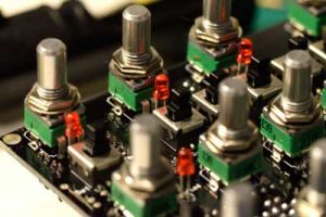
Installing the LEDs
Jacks
There was an issue with these, as the Thonkiconn jacks finish a little lower than the potentiometers, and I don’t have the panel to float them. Also, the Thonkiconn look different to the pictures and the 3rd extruding pin doesn’t solder in, but appears to be the ground rail connection. I decided to mount one how I thought it should go, and post a picture on the Synth DIY group on Facebook and The Muff Wigglers group. I got a few different recommendations including switching to the other recommended jacks, going ahead I had shown and not going ahead.
I decided to message Neutron Sound directly and they were very responsive. My initial assumption regarding the jack were correct, and they also clarified which ground to wire back to which wasn’t clear in the build guide (it’s the one marked kobi gnd).
Regarding floating the jacks a little so they line up to the future panel, I used the plastic washers I have to avoid rack rash and they spaced the jacks. I cut two of them into a C shape so I could pull them out and reuse them on each jack. This worked OK although I had to solder one pin at a time so I could hold it in place. I found that once I did one pin with the washer the other I could do freestanding. I also placed the jack to the extremities of the holes so they’d line up.
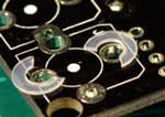
Spacing the jacks
With a bit of adjusting afterwards, I think the jacks lined up quite well, and the spacing from the PCB was consistent.
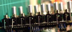
Final jack spacing
After that I put in the wire to ground and snipped off the excess legs from the jacks. I soldered the wire across and buzzed it out with a multimeter to ensure continuity. One problem, the excess wire was on the wrong side! I had a few things happening external so the lapse of concentration was perhaps understandable. Either way this was a quick fix. I decided I’d use a nicer black wire with sheathing to go back to ground.
Now I was ready to test!
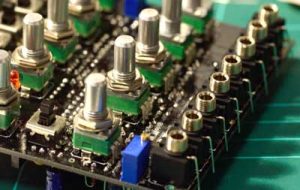
Thonikonn jacks installed
Pre IC Testing
Step one. Test ground connections from 10 ohm resistors (or beads). Working!
Then I had to get some power into it. I quickly made up a cable so I could connect to my workbench power supply.
I decided to connect the 5 volts first instead of 12 (my power supply is +-15v and +-5v). Smoke on one of the 10ohm resistors! Not good. Time for an inspection. Buzzing it out I could see there was shorts between the power and ground, however the soldering looked pretty spot on. But didn’t my continuity test work? I realise I must’ve misinterpreted the guide. So some deep inspection was needed.
I scraped a little around some of the closer connections then scrubbed with a toothbrush to try and get rid of excess solder… nothing. Then I when around with the soldering iron, trying to tidy up anything that had imperfection… still nothing. Then I saw a little bit of excess solder on a spare hole that looked innocuous, wiped it away, and bingo, the shorts in the power were gone! Test again… still shorting… what’s going on? Is it just the caps charging as mentioned in the guide? There seemed to still be a short between the +12v and ground.
I re-soldered some of the joints on the bypass capacitors which sit between the power and ground. Tested again, the temporary continuity was there but went away once the caps were charged. Time to connect the power again, but I noticed something when rechecking my cable… I had the positive and negative connections from the power supply to the bare ends of the cables swapped! So I fixed that, charged up the +-5v and the 10ohm resistor was no longer getting hot! Tried +-15V to check the regulator and everything was still fine. Now to move on. At least it validated my soldering was most likely spot on!
I measured the voltages at the legs of the two 10ohm resistors and that was fine. I also buzzed out the IC power pins to ensure they were OK as per the guide… all good.
Installing the integrated circuits
It was finally time to put in an IC, the reference buffer/driver op amp, in order to check the 3 volt inputs in the Teensy. It measure exactly +3.00 and -3.08 volts. Great!
Next was the three quad op amps. There’s mention in the build guide of a higher precision options using an LME49740. It was mentioned as an option in the build guide but I didn’t realise the benefit at the time. Thinking about it now the TL074 are pretty basic performance op amps, but I’ll use it now then I can swap it out later.
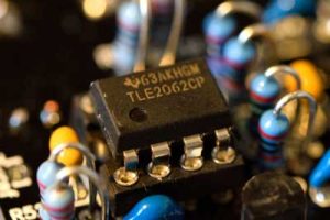
Installing the ICs
The sound check
First step, plug in a 1/Oct signal. In my case it was easier to plug in the random voltage from the Make Noise 0-Coast. Then.. Sound! Not the loudest output but something. The pitch was changing which was a good sign, but nothing else seems to work. All the LEDs don’t flash, and the pots do nothing. Back to the guide for troubleshooting!
I took the Teensy out and testing it on the computer, and it was fine. But with the Teensy back in the PCB it didn’t light up. The next few hours involved measuring some voltages and reading through the build thread to try and understand what was happening. I found a user that was getting similar issues and voltages, but there wasn’t an answer. I then turned my attention to the Teensy again, as this didn’t seem to be powering up, and it was only getting 2 volts instead of 3.3 volts. Back to the manual and where it say to cut the trace; was it really cut even though it looked it? The Teensy wasn’t supposed to power up from USB with it cut. A quick check with a multimeter and the answer was no. So I cut it, yet this wasn’t the only problem.
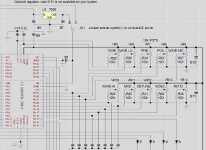
I turned my attention to how the Teensy was getting power, by looking at the schematic, specifically the part shown below. The potentiometers are on same power line as the Teensy AREF, and I was getting 2.9v at the pots, yes only 2v at the Teensy and the positive side of the bypass capacitor B8 (shown on the diagram as non-polarised but since updated). Given I was getting +-3 volts at the reference points, and 5v out of the regulators output, I didn’t understand why the Teensy was underpowered. So I started to look at the jumpers, J1, In and Ex as marked on the PCBs. My understanding from the build guide was that J1 should go to In for power via the regulator, or to Ex for an external 5v supply. I buzzed them out to see where they were going, and soon realised that to get the power from the regulator feeding into B9, I’d have to connect In to Ex. At some risk, I tried it out, and it worked!
Success, thoughts and cost summary
My Teensy powered up, as did the LEDs on the front. I plugged it and got proper sound, was able to add CVs in, use all the controls, everything was perfect! I still wondered whether my fix was to rectify another error in the build, or whether the guide out, but my first module, and probably one of the most complex builds, was done! I could also start to marvel at the sound and functionality of the module, each of the controls providing a lot of impact on the sound, and it felt like travelling down a modular rabbit-hole just within the module. Credit to Neutron Sound here is much deserved.
In the end the cost of all the components including delivery as AU$267, or around US$200, 190 euros or 160 pounds. Breaking that down it costs:
- AU$52 for the PCB delivered
- AU$6 for the Thonikonn jacks delivered
- AU$50 for the Teensy processor including delivery and USB cable
- AU$100 for all the components and hardware (resistors, capacitors, diodes, ICs, sockets, pins etc)
- AU$59 for the potentiometers
The stated price on Modular Grid is over US$400, so from a cost perspective the DIY version is around half price. If you added the labour though it’s probably 10 times more expensive! Nonetheless there’s great satisfaction in getting it done, and being one of the more difficult modules given the tight spacing, the Teensy,and the successful troubleshooting of its power, it gives me good confidence moving forward with the rest of the modules.
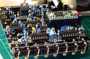
All the components installed
-3v reference calibration
Now that it was all done, I decided I’d complete the calibration as per the build guide. This was a matter of attaining certain settings and adjusting a trimmer until no sound could be heard.
Overclocking the CPU
I decided I’d follow the recommendation in the appendix and overclock the CPU. I had to connect the Teensy back to the computer whilst still on Eurorack power. From there you have to edit the boards.txt and uncomment the code for overclocking. However I couldn’t find the file, perhaps because I’m on Mac? I tried Finder and Spotlight search, searching Facebook and the build forum thread. Then I looked in the Arduino app and noticed there was already the 120Mhz overclock option, so I selected it. Then I uploaded the firmware and tested it again. All good.
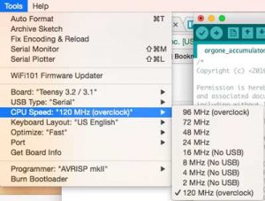
Overclocking the Teensy
More options!
In addition to all of the above, there’s also experimental code that comes with the oscillator, or you can make your own. The options are as follows and are something I’ll try:
- Mushroom delay 1 & 2
- Orgone Accumulator 2.5b1
- Orgone Accumulator All Drums 01
- Orgone Accumulator Fake Poly
And finally here’s the complete naked unit. Now onto the next!

Neutron Sound Orgone Accumulator

